MSD700 No.1005 – Rental Rover Guidebook
⚠️ Safety Precautions
Remote Operation Safety
This device can be operated remotely. Always ensure that the surrounding area is clear of people and objects before operating. Use brakes properly.
No Riding Policy
Do not ride on top of the device. This may cause tipping or accidents.
Load Capacity
When attaching additional equipment, do so within the load capacity. Use bolts and securely fasten them.
Crawler Maintenance
When reattaching a derailed crawler, be very careful to avoid hands getting caught in rollers or crawlers.
Battery Management
The device is powered by an internal battery. If voltage drops below the specified level, recharge immediately. Continued use under low voltage can cause battery damage requiring replacement.
Surface Restrictions
Do not operate on frozen surfaces. Operation on public roads is prohibited.
🛠️ Technical Specifications
Hardware
🔧 Main Components
Battery System
2 units (connected in parallel)
Drive Motors
2 units
Rubber Crawler
2 units
Control System
Advanced microcontroller
📋 General Specifications
Basic Information
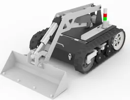
- Model Name: Micro Construction Machine
- Weight: Approx. 150 kg
- Drive System: Electrically powered crawler type
- Power Supply: Lithium-ion battery (DC 24V)
Performance
- Speed: 1.8 km/h
- Climbing Capability: 15° (25° tilting tolerance)
- Communication Range: Up to 200 m (line of sight)
- Environmental Protection: Approx. IP54
Power & Charging
- Operating Voltage: 29.7 V ~ 21.0 V
- Charger: Dedicated charger (AC 100V)
🔍 Detailed Equipment Specifications
Battery System
Motor System
Rubber Crawler
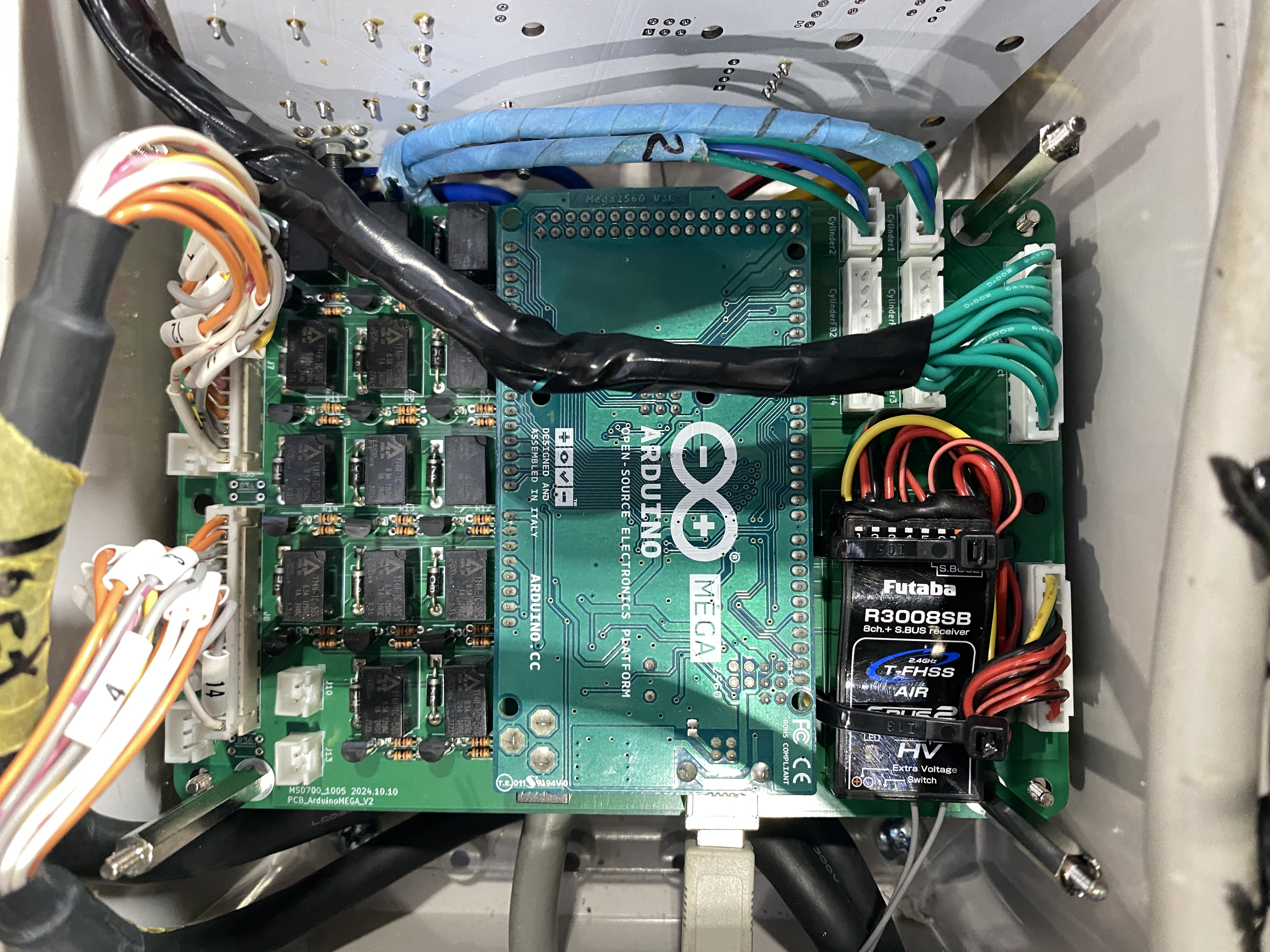
Control Unit
Software
💻 Source Code Repository
Arduino Source Code
Description: Complete Arduino source code for MSD700 No.1005 control system including motor control, sensor integration, and communication protocols.
Wiring Diagram
🔌 Complete System Architecture
Overview of the entire electrical system including power distribution, control units, and sensor connections
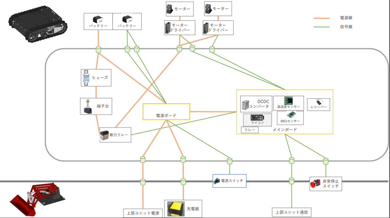
Complete System Architecture
Comprehensive electrical system layout showing power distribution, control units, and interconnections
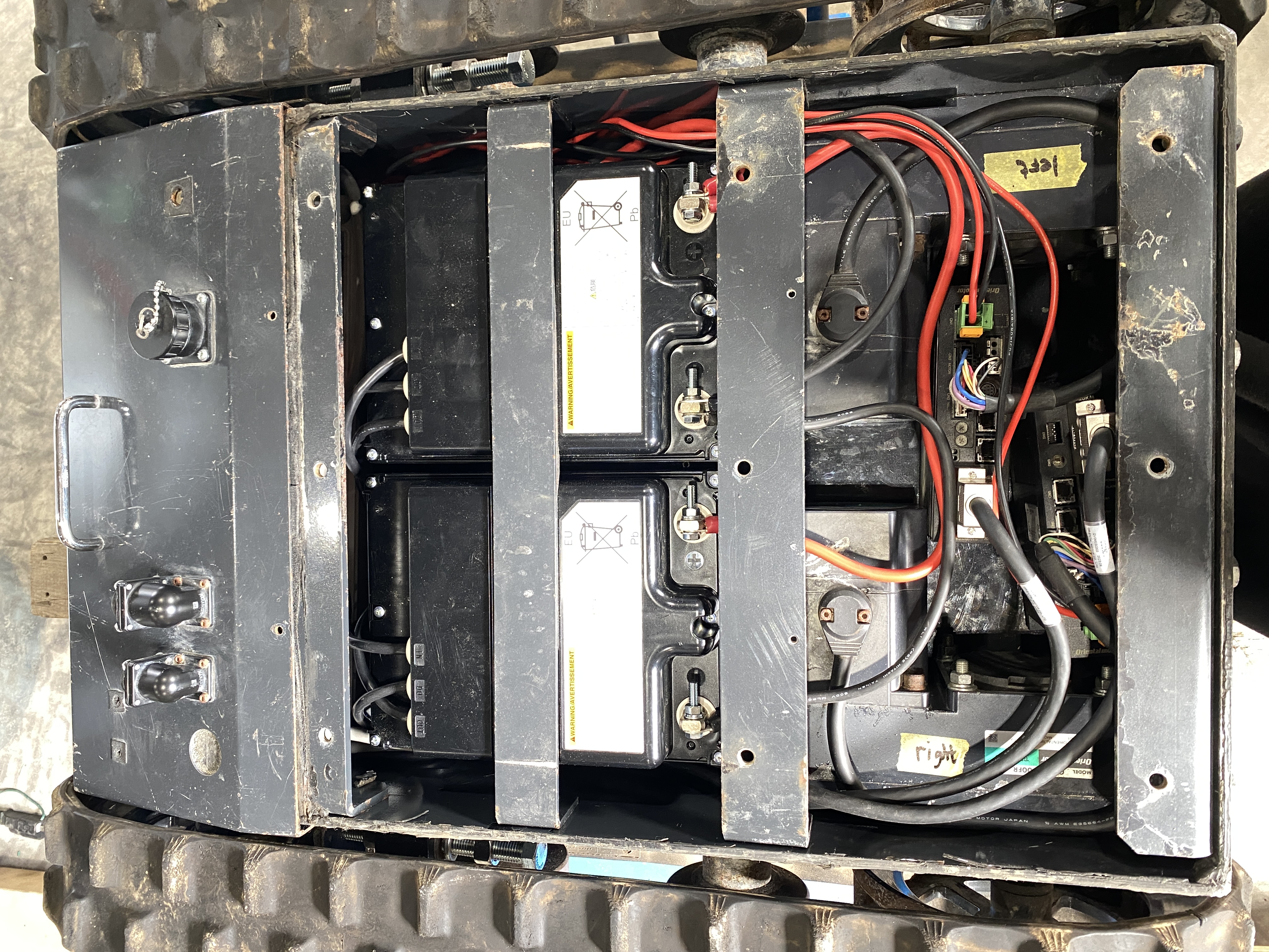
🔋 Battery Connection Details
Detailed battery wiring configuration and parallel connection setup
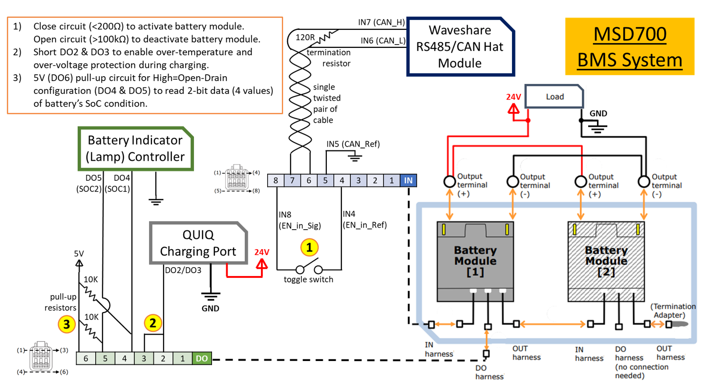
Battery Parallel Connection Setup
Detailed wiring schematic for parallel battery configuration
Battery Unit 1
Parallel Configuration
Battery Unit 2
⚠️ Battery Safety Guidelines
- Ensure proper polarity when connecting batteries
- Use appropriate gauge wire for current capacity
- Install fuses on positive terminals
- Monitor battery temperature during operation
- Follow manufacturer's charging procedures
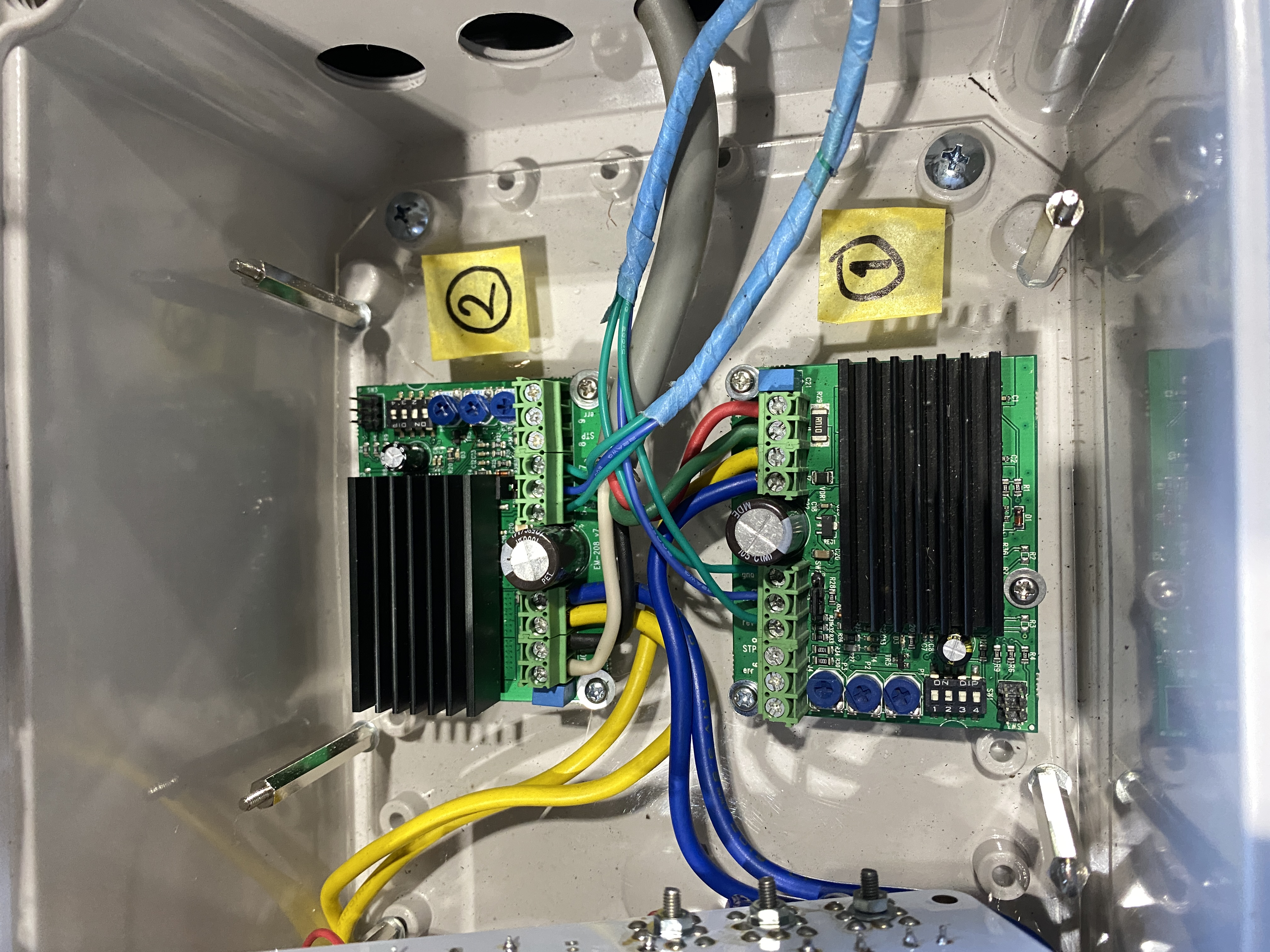
🔧 Physical Wiring Implementation
Step-by-step wiring process and connector details for field installation
📸 Actual Installation Photos
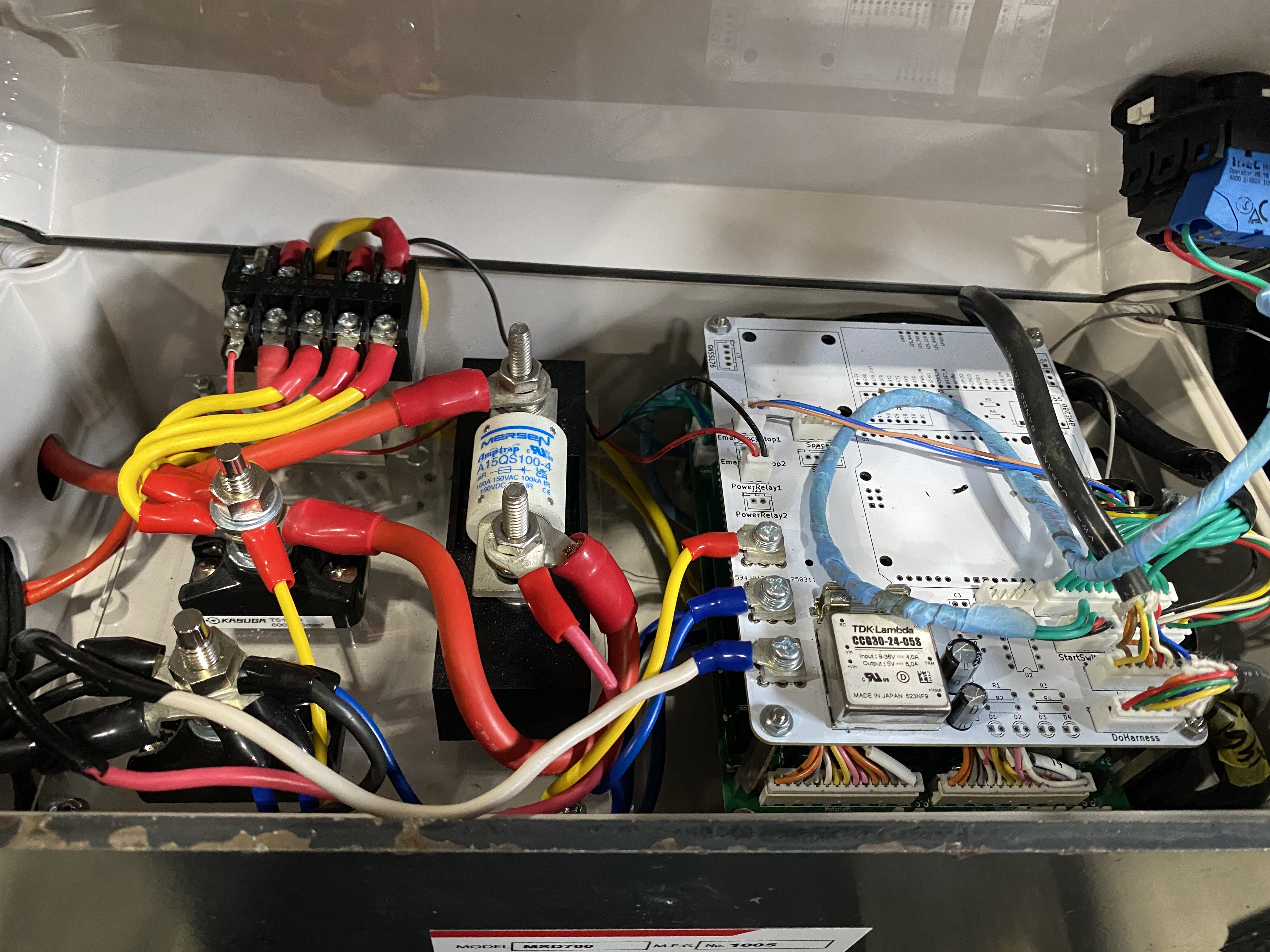
Power Distribution Setup
- Connect battery positive terminals together
- Connect battery negative terminals together
- Install main power switch on positive line
- Add fuse protection (30A recommended)
Controller Connections
- Connect main power to controller input
- Wire control signals to motor drivers
- Establish communication lines
- Connect emergency stop circuit
Motor Driver Wiring
- Connect motor driver power inputs
- Wire three-phase outputs to motors
- Connect encoder feedback signals
- Install thermal protection
📋 Connector Specifications
PCB Circuit Diagram
🔧 Unified PCB Design
Shared circuit board design for MSD700 models 1005, 1006, and 1007 ensuring consistency and cost-effective manufacturing.
📄 PCB Circuit Diagram Document
Complete circuit schematic and board layout for MSD700 Bucket Model PCB
📊 PCB Technical Specifications
📐 Physical Dimensions
⚡ Electrical Specifications
🌡️ Environmental Ratings
🔧 Manufacturing Standards
🔧 Component Layout & Placement
Power Management Zone
Microcontroller Zone
Motor Driver Zone
Communication Zone
🏭 Manufacturing & Assembly Notes
Production Guidelines
- ✓ Automated SMT assembly recommended
- ✓ Reflow profile: Lead-free SAC305
- ✓ AOI (Automated Optical Inspection) required
- ✓ In-circuit testing (ICT) for all power rails
- ✓ Conformal coating for outdoor use
- ✓ Final functional testing mandatory
Assembly Sequence
- Step 1: SMT component placement
- Step 2: Reflow soldering
- Step 3: Through-hole components
- Step 4: Wave soldering
- Step 5: Cleaning & inspection
- Step 6: Programming & testing
- Step 7: Final quality check
Critical Notes
📋 Revision History
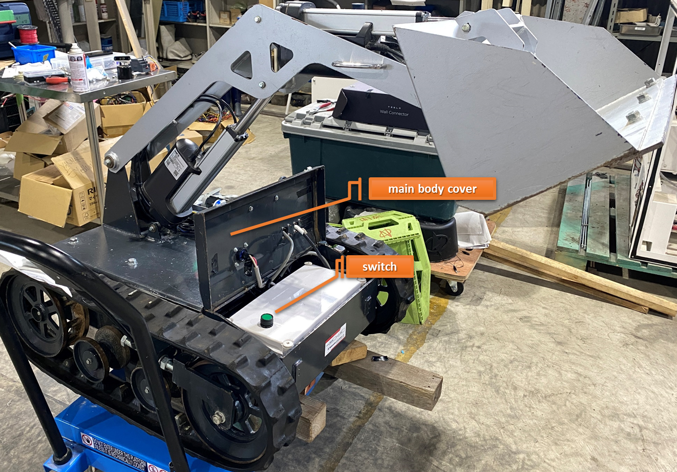
🎮 Operation Methods
Power On Procedure
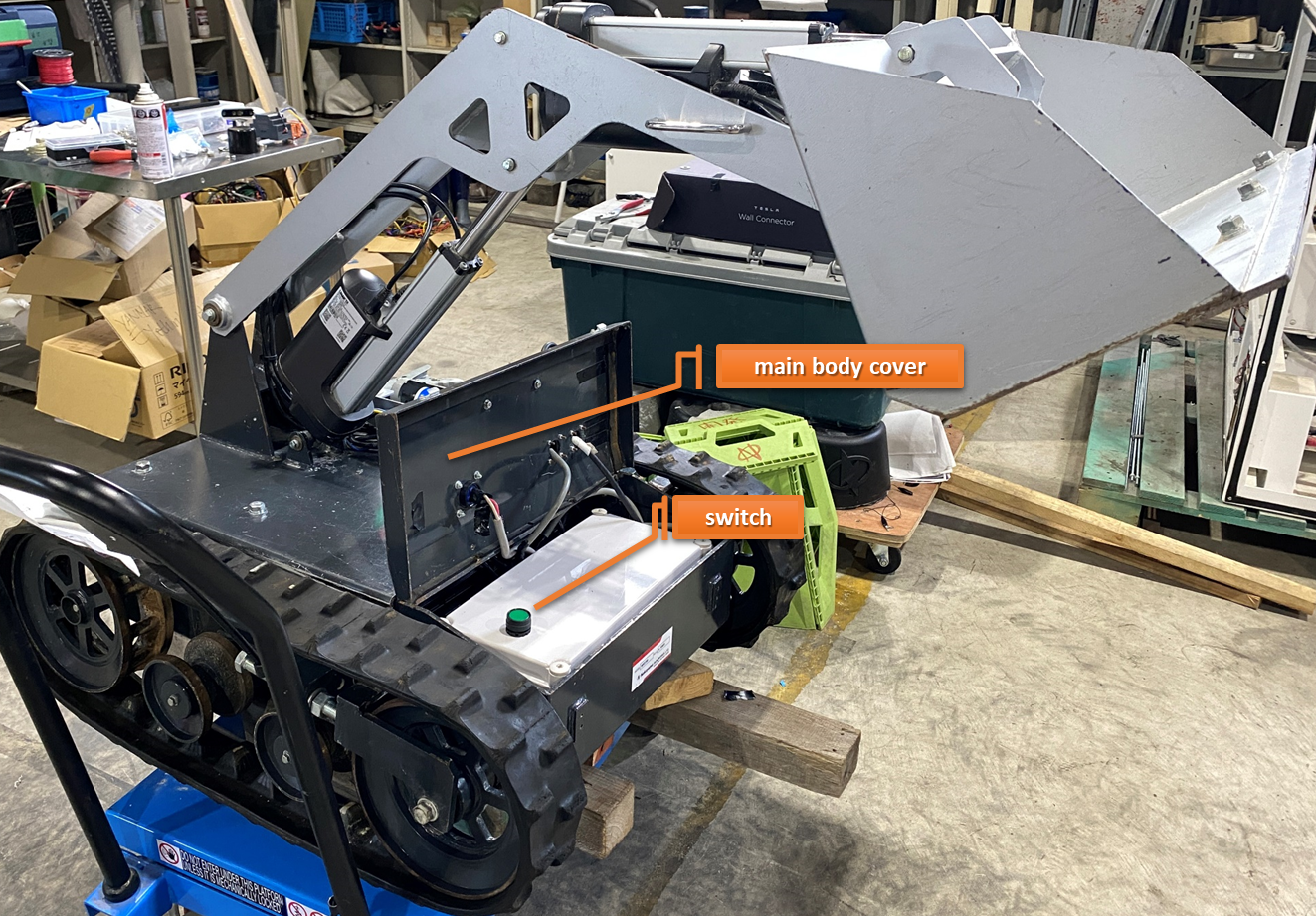
Open the Main Body Cover
Carefully open the main body cover to access the internal components and power controls.
 Main body cover opening procedure
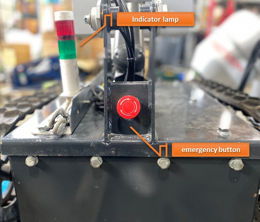
Press Main Power Switch
Press the main power switch and confirm that the power indicator lamp lights up green, indicating successful power activation.
 Power switch activation and green indicator confirmation
Release Emergency Stop Button
Release the emergency stop button to complete the power-on sequence and enable full system operation.
Control Methods
Futaba Radio Controller
This MSD700 is controlled using a Futaba radio controller for precise remote operation.
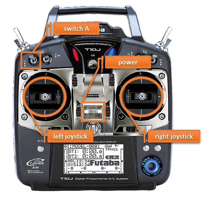 Futaba radio controller with joystick and switch layout
Turn On Controller
Turn on the controller by switching the power switch to ON position.
Activate Motor & Arm Power
Flip Switch A downward to enable motor and arm power.
Motor Control
Use the left joystick to control the motor movement and navigation.
Arm Control
Use the right joystick to control the robotic arm operations.
Shutdown Procedure
Safe System Shutdown
Follow these steps carefully to ensure safe shutdown of the MSD700 system.
Press Emergency Stop Switch
Immediately press the emergency stop switch to halt all system operations safely.
Raise Switch A
Move Switch A to the upward position to disable motor and arm power.
Turn Off Controller Power
Switch the controller power to OFF position after ensuring Switch A is in the up position.
Main Power Switch OFF
Open the main body cover and switch the main power switch to OFF position.
Safety Reminders
- Always press emergency stop first
- Ensure Switch A is raised before powering off controller
- Wait for all moving parts to stop completely
- Confirm all indicators are off before closing covers
⚡ Charging Procedure
Precautions
Important Safety Precautions
Please read and follow these safety precautions carefully before charging the MSD700 system to ensure safe operation and prevent accidents.
Electrical Safety
Avoid touching metal pins on the charging plug or connector to prevent electric shock.
Cleanliness & Dryness
Ensure the charger, connectors, and cables are clean and dry before use.
Designated Equipment Only
Use only the designated charger and charging connector supplied with the unit.
Voltage Verification
Confirm that the AC outlet voltage matches the specified rating (AC 100 V).
Dry Hands Required
Do not operate the charger or main unit with wet hands.
Fire Prevention
Keep flammable materials away from the charging area.
Cable Protection
Do not place heavy objects on charging cables to prevent damage.
Emergency Contact
If you notice any abnormal conditions during charging (sparking, unusual heat, strange odors), immediately disconnect the power and contact technical support.
Battery Connection
MSD700 Charging Procedure
Follow these steps carefully to properly charge the MSD700 system using the designated charger and connections.
[Charger] Attach Charging Connector
If not already connected, attach the charging connector and charger plug to the charger.
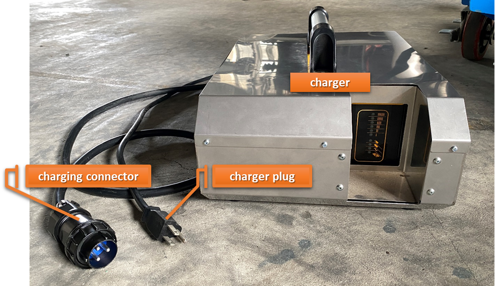 Attach charging connector to charger
[Main Unit] Connect to Charging Port
Connect the charging connector to the main unit's charging port securely.
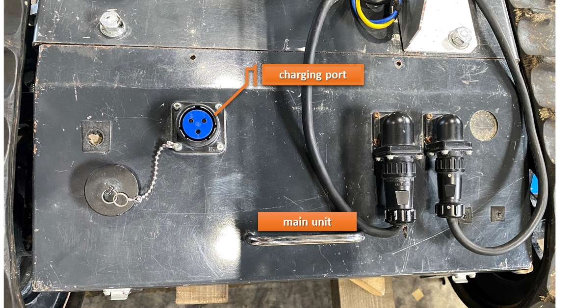 Connect to main unit charging port
[Main Unit] Switch ON Internal Power
Switch ON the internal power switch of the main unit to enable charging mode.
 Activate internal power switch
[Charger] Plug into AC 100V Outlet
Plug the charger into an AC 100 V outlet. Ensure voltage compatibility before connection.
[Charger] Turn ON Charger Switch
Turn ON the charger switch to begin the charging process.
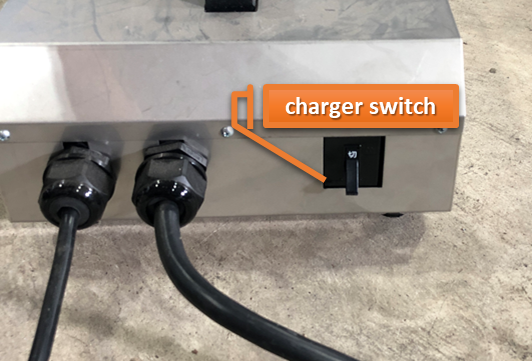 Turn ON charger switch
✅ Charging Active
Charging will begin — check the charger indicator lights to confirm proper operation.
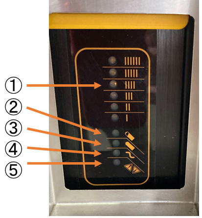
Indicator Lights
Charger Status Indicators
Monitor these indicator lights on the charger to understand the charging status and ensure safe operation of the MSD700 system.
 Charger indicator lights panel
【Ammeter (Orange)】
【Bulk Charging Indicator (Orange)】
【Charge Complete Indicator (Green)】
【AC Indicator (Orange)】
【Error Indicator (Red)】
Charging Behavior & LED Sequences
When AC Power is Applied
Typical LED Indications
Charging Started
Battery Charged Over 80%
Charging Complete
Note:
Charging will not automatically restart.
To recharge, turn off the charger, wait 30 seconds, then turn it back on.
🔧 Abnormalities and Countermeasures
If the error indicator (⑤) blinks, refer to the table below to identify the issue and apply the appropriate countermeasure. The number of blinks indicates the specific type of error.
| Number of LED Blinks | Abnormality | Charging Forced Stop | Detection Threshold | Countermeasure |
|---|---|---|---|---|
|
1
blink
|
Battery voltage too high
|
Recovers after avoidance
|
Voltage above 28.6 V
|
Charging automatically resumes when battery voltage returns to normal operating range
|
|
2
blinks
|
Battery voltage too low
|
Recovers after avoidance
|
Voltage below 16.5 V
|
Charging automatically resumes when battery voltage returns to normal operating range
|
|
3
blinks
|
Charging time exceeded
|
Forced stop
|
CC mode: over 2.5 hours
CV mode: over 0.5 hours
|
Unplug AC power, wait 30 seconds, then reconnect AC power to restart charging
|
|
4
blinks
|
None
|
—
|
—
|
—
|
|
5
blinks
|
Charger temperature too high
|
Forced stop
|
Output turns off at internal temp 83°C
|
Charging restarts when temperature drops, but error clears only after unplugging AC power for 30 seconds and reconnecting
|
|
6
blinks
|
Charger internal fault / DC wiring connection failure
|
Forced stop
|
- Charger internal fuse blown
- Battery wiring loose
- Other internal faults or failures detected
|
Check DC wiring, unplug AC power for 30 seconds and reconnect; if error persists, contact dealer
|
📕 Description
Document Information
MSD700 Technical Documentation
Contact Information
Technical Support & Documentation